Request a Quote
ma
Leave Your Message

How to Choose the Right Electric Lift Actuator?

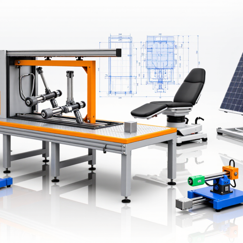
Choosing the right Electric Lift Actuator begins with the real movement your equipment must perform. A workshop table, medical chair, solar panel, and industrial hatch all need different solutions. Their loads, travel distances, speeds, and operating environments can vary sharply. A compact actuator may lift 500 newtons, yet fail under repeated side loading. That detail is easy to miss.

Start by measuring the application, not guessing from appearance. Record the required force, stroke length, retracted length, lifting speed, duty cycle, and mounting space. Consider the load’s center of gravity. A 300-kilogram load placed far from the pivot can demand much more force than its weight suggests. Mechanical calculations should include friction, leverage, acceleration, and a suitable safety margin. When possible, confirm these values through testing.

Electrical and environmental conditions matter just as much. Check the available voltage, current capacity, control method, limit-switch design, noise expectations, and emergency stopping requirements. Dust, moisture, vibration, and temperature may require a higher IP rating or stronger housing. Feedback options, such as potentiometers or Hall sensors, can improve position control. However, they also add cost and integration work.

A reliable choice balances performance, service life, installation effort, and total cost. Do not select the strongest model automatically. Oversized actuators may consume more power and create unnecessary structural stress. Manufacturer test data, clear drawings, warranty terms, and technical support deserve careful review. Small oversights can become expensive failures. My own preference is to prototype early, because specifications rarely reveal every alignment problem. Leave room to revise the design.

How to Choose the Right Electric Lift Actuator?

Define the Application and Required Actuator Movement

How to Choose the Right Electric Lift Actuator?

Define the Application and Required Actuator Movement

Choosing an electric lift actuator begins with the movement your equipment must perform. Start with the load, lifting direction, stroke length, and available installation space. A kitchen cabinet may need 100 millimeters of quiet travel. A medical platform may require longer movement and precise positioning. Measure the distance between fully retracted and fully extended positions. This measurement defines the required stroke. That is not enough. Record the movement speed and operating frequency too. An actuator lifting a cover twice daily faces different demands from one cycling every minute. I have seen small design errors cause binding, noise, and early wear.

Tips: Create a simple movement sketch before selecting an actuator. Mark pivot points, mounting holes, load direction, and nearby obstacles. Write down the maximum load, not only the normal load. Check whether the load changes during travel. Leave room for wiring and maintenance. Do not guess.

Review the application under real operating conditions. An actuator may support the weight statically but struggle during startup. Friction, uneven loading, and side forces can increase the required force. Keep side loads away from the actuator whenever possible. Confirm the duty cycle, voltage, environmental exposure, and emergency stopping needs. For outdoor equipment, consider water, dust, temperature, and corrosion. Technical data should be checked against independent calculations and test results. A useful margin is wise, but excessive capacity can add cost and reduce efficiency. My own first estimates have sometimes been too optimistic. Rechecking the movement usually reveals why.

How to Choose the Right Electric Lift Actuator?

Define the application first, then select an actuator with enough stroke length to complete the required movement. The chart shows representative linear travel requirements for common lifting applications.

Typical movement values: cabinet and hatch mechanisms generally require short travel, adjustable workstations require medium travel, and lifting platforms may require long travel. Always confirm the required stroke, load, speed, duty cycle, mounting space, and safety margin before choosing an actuator.

Calculate Load, Force, Speed, and Stroke Requirements

How to Choose the Right Electric Lift Actuator?

Start with the real load, not the product label. For a vertical lift, calculate F = m(g + a) + Friction + Process Force. Here, m is the total moving mass, including fixtures. Use 9.81 m/s² for gravity. Measure friction when possible. A dry guide can change the result significantly. Add an engineering margin, commonly 1.5 to 2.0, then verify it through testing. My first sizing sheet ignored acceleration. That shortcut was wrong.

Speed comes from the required motion. Divide stroke by travel time, then check whether acceleration limits affect the cycle. A 400 mm stroke completed in 8 seconds needs 50 mm/s average speed. The actuator may need higher peak speed. Stroke should include working travel, alignment tolerance, and safe clearance.

Do not use the mechanical end stop as normal positioning control. Record cycles per hour, duty time, pauses, and ambient temperature. These details often expose an unsuitable actuator.

Power can be estimated with P = Fv/η, where η represents system efficiency. Select the actuator above the calculated continuous force, not only the peak force.

The U.S. Department of Energy’s United States Industrial Motor Systems Market Assessment reports that motor-driven systems used about 23% of U.S. electricity, showing why efficiency deserves attention. The IEA’s Energy Efficiency 2023 report states that industry represented nearly 37% of global final energy demand in 2022.

Check guarding and risk controls against ISO 12100 and IEC 60204-1. Numbers help, but field measurements remain decisive.

Compare Actuator Types, Power Sources, and Control Options

How to Choose the Right Electric Lift Actuator?

Selecting an electric lift actuator starts with the load, stroke, speed, and duty cycle. Rod-style actuators suit guided platforms with moderate travel. Screw-driven column actuators offer better stability for vertical lifting. Track actuators can handle longer movement but may need stronger structural support. Check side-load limits carefully. A heavier actuator is not always safer.

Power sources change real-world performance. AC systems fit fixed industrial equipment and continuous operation. DC systems work well in mobile machines, battery platforms, and backup applications. The IEA’s Energy Efficiency 2023 report estimates that electric motor systems consume about 53% of global electricity. Even small efficiency gains deserve attention. Measure standby consumption, peak current, and heat around the actuator. A neat spreadsheet can mislead.

Control options include simple switches, relays, programmable controllers, and networked feedback systems. Position sensors improve repeatability, while current monitoring can reveal overloads before mechanical damage occurs. For equipment safety, review IEC 60204-1 and ISO 12100 during design. In practice, I test the actuator with the actual frame, not only a bench load. Flex, friction, and uneven mounting often reduce expected capacity. I still allow extra margin, although excessive margin increases cost and energy use. That trade-off needs honest review.

Evaluate Environmental Ratings, Safety Features, and Durability

Choosing an electric lift actuator starts with the environment, not lifting force alone. Check the enclosure rating for dust and water exposure. An outdoor platform may face driving rain, mud, salt spray, and freezing nights. An indoor medical table has different risks. Match the rating to the actual installation, not the brochure’s best-case picture. IP numbers help, but they do not describe chemical resistance or impact strength. Fit matters.

Safety features deserve direct testing. Look for overload protection, dependable limit switches, emergency stopping, and controlled movement after power loss. A manual release can matter when the load must be lowered safely. Confirm that force, stroke, speed, and duty cycle suit the mechanism together. One oversized unit can damage hinges or create dangerous pinch points. Keep guards around moving parts. Test the full assembly, not only the actuator on a workbench. Small alignment errors can become loud vibration.

Durability depends on cycles, side loads, maintenance, and installation quality. Ask for cycle-test data, temperature limits, corrosion testing, and clear inspection intervals. Check cable strain relief and mounting hardware; these details often fail first. Test it cold. Compare real duty requirements with a reasonable safety margin. Too much margin can increase cost and energy use. Too little leaves no room for wear. That judgment is not always obvious. Recheck it after measuring the actual load, especially when friction changes during seasonal use.

Select a Compatible Actuator and Verify Installation Requirements

Choosing the right electric lift actuator starts with compatibility, not maximum force. Confirm the lifted mass, center of gravity, stroke length, speed, and duty cycle. A 1,000-newton rating may fail if the load creates side pressure or frequent shock.

According to the International Energy Agency’s Energy Efficiency 2023 report, motor-driven systems use roughly half of global electricity. Efficiency matters, but installation conditions matter more. Match the actuator’s voltage, control signal, mounting points, and retracted length with the equipment. Check the IP rating for dust, water, and cleaning exposure. Verify whether the actuator can hold position without power. That detail is often missed.

Leave clearance around moving joints and protect cables from bending or abrasion. Confirm limit-switch settings before applying the full load. For machinery, review ISO 12100, ISO 13849, and IEC 60204-1 requirements with a qualified engineer. These standards help address hazards, control reliability, and electrical safety. A practical test should measure current draw, travel time, noise, and temperature after repeated cycles. A neat spreadsheet is not enough. I have seen installations pass a static test, then overheat during real production. Recheck alignment under the actual load. Minor frame flex can become a serious failure point.

How to Choose the Right Electric Lift Actuator? - Select a Compatible Actuator and Verify Installation Requirements
Selection Dimension Typical Requirement or Data Range How to Select a Compatible Actuator Installation and Application Verification
Load Capacity Common light- and medium-duty electric actuators: approximately 500–4,500 N rated force. Select an actuator whose rated push and pull force exceed the calculated working load. Include the weight of the lifted object, friction, and a safety margin. Confirm whether the load is axial. Side loads, uneven loading, or bending forces can damage the actuator and should be supported by external guides or hinges.
Required Stroke Length Typical available strokes range from approximately 50 mm to 600 mm, depending on the actuator design. Choose a stroke equal to the actual travel required by the mechanism. Avoid selecting excessive stroke because it can increase retracted length and installation space. Measure the fully closed and fully open positions. Check that the actuator does not reach its internal limit before the mechanism reaches its intended end position.
Operating Speed Typical linear speed: approximately 5–50 mm/s. Higher loads generally reduce achievable speed. Choose speed according to the required cycle time, load, and control precision. A slower actuator is often preferable where positioning stability is important. Calculate cycle time using stroke length divided by rated speed. Verify that the actuator can complete the required duty cycle without overheating.
Duty Cycle Common ratings include intermittent operation such as 10% duty cycle, often expressed as a few minutes of operation per hour. Match the actuator duty rating to the number of cycles, operating time, and rest time required by the equipment. Do not operate an intermittent-duty actuator continuously. Check the manufacturer’s stated on-time, off-time, and maximum cycles per hour before installation.
Power Supply Frequently used DC input voltages include 12 VDC and 24 VDC. AC-powered systems may require an external power supply or controller. Select an actuator voltage compatible with the available system voltage. The power supply should also provide sufficient current during startup and peak load. Check polarity, connector wiring, fuse protection, voltage drop, and emergency-stop requirements. Use a suitable relay, switch, or motor controller for reversing direction.
Mounting Geometry Important dimensions include retracted length, extended length, mounting-hole spacing, and mounting-pin diameter. Select an actuator that physically fits the available envelope and provides the required extension without binding. Verify both mounting points in the closed and open positions. The actuator should pivot freely and should not be forced to absorb structural misalignment.
Mounting Orientation Orientation limits vary by actuator construction. Some models permit horizontal or vertical installation, while others require a specific position. Choose an actuator with an installation orientation suitable for the equipment and environmental conditions. Follow the specified orientation for drainage, lubrication, limit-switch operation, and protection against water or debris entering the housing.
Limit Switches Internal fixed limit switches are common; adjustable external or internal limits may be available for certain applications. Select fixed limits when the travel is standardized. Select adjustable limits when the mechanism requires accurate, variable end positions. Test both end positions at low risk before applying the full load. Do not rely on the actuator’s internal limits to stop a mechanism that can move beyond its safe range.
Feedback and Position Control Optional feedback methods may include potentiometer, Hall-effect sensor, encoder, or no feedback. Use no feedback for simple two-position movement. Use feedback when the control system needs position monitoring, synchronization, or repeatable intermediate positioning. Confirm feedback output type, voltage range, resolution, connector pinout, and compatibility with the control system before wiring.
Ingress Protection Enclosures may be rated from basic protection to high water- and dust-resistance levels; an IP rating must be checked for the complete assembly. Choose an ingress-protection level based on dust, rain, washdown, humidity, and outdoor exposure. Inspect cable glands, connectors, seals, and mounting orientation. The actuator’s protection rating does not automatically apply to the power supply or controller.
Operating Temperature Many industrial actuators operate within a range near −20°C to +65°C, but the actual range depends on materials, lubrication, and electronics. Select a temperature rating covering the lowest and highest ambient temperatures at the installation site. Consider heat generated by repeated operation, direct sunlight, cold-start conditions, and reduced battery performance at low temperatures.
Noise Level Typical mechanical actuator noise may be approximately 50–70 dB(A), depending on load, speed, gearing, and mounting. For furniture, medical, laboratory, or office equipment, prioritize a low-noise gear system and controlled acceleration. Mount the actuator securely and isolate vibration where appropriate. Loose brackets and resonant panels can make the system louder than the actuator itself.
Mechanical Backlash Screw-driven actuators may have measurable clearance between the screw and nut, which can affect repeatability. Choose a low-backlash design when accurate positioning or stable load holding is required. Determine whether the actuator is intended to hold the load when power is removed. Add a mechanical brake, lock, or external support when uncontrolled movement would be hazardous.
Safety and Overload Protection Possible protective features include thermal overload protection, current limiting, clutch protection, and mechanical end stops. Select protection appropriate to the risk level, load variation, and likelihood of obstruction or jammed movement. Install external current protection and emergency stopping where required. Test stall, obstruction, and power-loss conditions before commissioning.
Structural Alignment The actuator should transfer force along its intended axis without significant lateral or twisting load. Use guided mechanisms, clevis joints, pivot brackets, and parallel actuators when the application requires controlled alignment. Move the mechanism manually through its full range before connecting power. Check for binding, unequal loading, excessive deflection, and interference.
Environmental and Material Compatibility Materials may include painted steel, stainless steel, aluminum, and engineering plastics, depending on corrosion and weight requirements. Select materials compatible with moisture, salt, cleaning chemicals, ultraviolet exposure, and the expected service life. Confirm fastener materials, galvanic-corrosion risks, cable protection, and cleaning procedures. Avoid exposing seals and coatings to chemicals outside their ratings.
Important: Actual force, speed, duty cycle, dimensions, protection rating, temperature range, and wiring requirements vary by actuator model and application. Verify the technical datasheet, load calculations, electrical design, and applicable safety requirements before installation.